Showing posts with label BOSE AUDIO. Show all posts
Showing posts with label BOSE AUDIO. Show all posts
Friday, June 17, 2016
BOSE SoundDock – Disassembling procedure – Step by Step disassembling procedure – Audio system repair and service

Category: Audio System Repair and Service
Contents of this article
- How to disassemble the Dock Cradle
- Docking PCB removal
- Amplifier removal
BOSE SoundDock
DISASSEMBLE PROCEDURES
1. Docking Cradle Assy Removal
1.1 Remove the four Phillips-head screws located on the bottom side of the docking cradle assembly. See figure
1.1 Lift the docking cradle assembly slightly away from the speaker enclosure and disconnect the 20 conductor flexible flat cable (FFC) before removing the cradle Assy completely.
Note: This cable provides signal paths between the amplifier and digital signal processor PCB’s.

2. DSP PCB Removal
2.1 Remove the cover from the Cradle Assy and note the orientation of the 24 conductor FF cable prior to disconnecting it from the Digital Signal Processor (DSP) PCB. Ensure that the foam protection on the cable is facing the cradle cover upon reinstallation. See figure
2.2 Slide the DSP PCB out of the cradle housing and disconnect the 24 conductor FF cable. See figure
2.2 Slide the DSP PCB out of the cradle housing and disconnect the 24 conductor FF cable. See figure

3. Docking PCB removal
3.1 Remove three torx-head (T7) screws as shown in figure
3.2 Inspect the docking connector for signs of excessive wear and replace if necessary.
3.2 Inspect the docking connector for signs of excessive wear and replace if necessary.


4. Grille Removal
4.1 Carefully push the bottom edge of the grille up using your thumbs while pushing down on the speaker housing with your index fingers as shown in figure
4.2 Work the remaining sides of the grille up until it is completely disengaged from the SoundDock.
4.3 Inspect the grille for damage and replace it if necessary.
4.2 Work the remaining sides of the grille up until it is completely disengaged from the SoundDock.
4.3 Inspect the grille for damage and replace it if necessary.

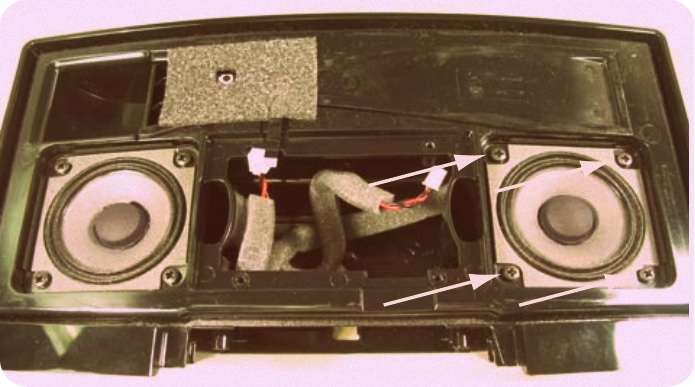
5. Amplifier PCB Assy Removal
5.1 Remove the four Phillips-head screws securing the Amplifier PCB Assy to the speaker housing as shown in figure
5.2 Using the heatsink fins and FF cable, carefully lift the Amplifier PCB Assy away from the speaker housing.
5.3 Disconnect the IR Receiver PCB FF cable and the Left & Right driver cables from the Amplifier PCB.
5.4 Amplifier PCB, see figure
5.5 Position the left and right driver harness as shown in figure. This will ensure that you don’t confuse the phasing of the drivers when reconnecting them to the PCB


6. Infrared Receiver PCB Removal
6.1 Peel back the foam tape concealing the IR Receiver PCB. See figure for details
6.2 Remove the Phillips-head screw securing the PCB in place
6.3 Disconnect the four conductor FF cable from the IR PCB.
Note: This cable provides signals to the
DSP IC via the Amplifier PCB.
6.2 Remove the Phillips-head screw securing the PCB in place
6.3 Disconnect the four conductor FF cable from the IR PCB.
Note: This cable provides signals to the
DSP IC via the Amplifier PCB.


7. Driver removal
7.1 Remove four phillips-head screws securing the driver to the speaker housing. See Figure
7.2 Note the routing of the driver harness before fully extracting the driver. See figure
7.3 Ensure acoustic foam is positioned behind the driver. See figure
7.2 Note the routing of the driver harness before fully extracting the driver. See figure
7.3 Ensure acoustic foam is positioned behind the driver. See figure

Thursday, June 16, 2016
BOSE LIFESTYLE 135 - BOSE Cinemate 1SR – Pairing the bass module and sound bar – performance test – audio system repair and service

Category: Audio System Repair and Service
Contents of this article
- Paring procedure
- Test procedure
BOSE LIFESTYLE 135
Pairing a Sound Bar to a Bass Module
Overview
The sound bar RF ID is stored in the bass module. Once the RF ID is stored, the sound bar will only communicate to the bass module it has been paired with. If you are testing a customer soundbar or bass module with a test soundbar or bass module, it is necessary to pair the customer device to the bench test device. If you pair a customer soundbar or bass module to a test device, provide the customer instructions to pair their system when returned. A maximum of four paired sound bar and bass modules can operate in close proximity.
Wired Connection
If using in an application such as a hotel or areas where RF interference might occur, a SMB wired connection should be used. When using the wired connection, the sound bar will pair automatically with the bass module. 331731-0010 : 4 meter SMB to SMB Coax Cable (used for end user wired connection) 345328-0010 : 1 meter SMB to F Coax Cable (two used for wiring up to 100’)
1. CineMate 1SR End User Pairing Instructions
1.1 Unplug the Acoustimass module AC power cord.
1.2 Remove the door on the end of the speaker array.
1.3 Press and hold the ADAPTiQ button for 3-4 seconds until the status indicator starts slowly blinking orange.
1.4 Plug the Acoustimass module AC power cord in the AC outlet.
Pairing is complete when the Acoustimass module status indicator becomes solid orange and the speaker array status indicator turns off.
2. Lifestyle 135 End User Pairing Instructions.
2.1 Using the system cable, connect the soundbar to the control console.
2.2 Apply power to the console, soundbar, and bass module.
2.3 Press the Setup button on the control console and select the “Reconnect Acoustimass” menu item..
3. Pairing using a SMB cable
3.1 Connect SMB cable, part number 331731-0010, to the sound bar and bass module.
3.2 Connect power to the soundbar and bass module.
3.3 A solid orange LED on the bass module indicates paring is complete.
3.4 To avoid the soundbar or bass module from pairing with another system in the repair area, remove power from both components before removing the SMB cable.
Setting The Region Variant – CineMate 1SR Only
1. Setting the Region Variant - CineMate 1SR Only
There are 4 variants of the CineMate 1 SR sound bar (US/AIM, EURO/UK, Asia Pacific, Japan) that have separate AdaptiQ language lists. When replacing DSP PCB in a US, Asia/PAC, and Japan variant, the variant needs to be set to present the proper AdaptiQ language selection list. The UK/EURO variant does not need to be set. The US, Asia/PAC, and Japan version use the same version of a programmed IC containing the language list. The EU/UK version uses a programmed IC that contains just the EU/UK langue list.
1.1 Issue TAP commands.
1.2 Enter the TAP command TN 65 ON, to turn on the sound bar.
1.3 Enter the appropriate TAP command from the table below to set the variant
US TN 33 1
Asia/Pac TN 33 3
Japan TN 33 4
Asia/Pac TN 33 3
Japan TN 33 4
Lifestyle 135 Performance Verification Procedures
Required Equipment
1. Tera Term terminal emulator - download at sourceforge.jp/projects/ttssh2/
2. TAP cable 264565 ( used for TAP commands)
3. TAP cable 299656 (used for COAX input and Turn on voltage)
4. An A/D converter and audio generator
5. Lifestyle 135 Bass Module
6. SMB cable part number 331731-0010 or equivalent.
7. Computer setup to issue TAP commands
8. A paired soundbar and bass module -
1. Sound Bar Air Leak Test
1.1 Issue the following TAP commands
SO BDSP (resets DSP)
SO L,ALL (sends left input to all channels)
SO 0,8 (mutes bass channel)
VO CB 20 (sets volume level)
1.2 Apply a 285 Hz, 85 mVrms signal to the A/D converter.
1.3 Listen for any air leaks from sealed enclosures for the twiddlers, tweeter, and phase guide arrays.
2. Sound Bar Buzz Test and Sweep Test
2.1 Issue the following TAP commands
SO BDSP (resets DSP)
VO CB 20 (sets volume level)
SO 0,8 (mutes bass channel)
2.2 Apply a 200 Hz, 85 mVrms signal to the left input of the A/D converter.
2.3 Sweep the audio generator form 200 Hz to 2 kHz.
2.4 Listen for buzz, rub, or extraneous sounds.
Localize and repair any buzz. Replace any transducer that rubs or produces extraneous sounds.
2.5 Issue the TAP command VO CB 20 to set the volume level.
2.6 Apply a 200 Hz, 60 mVrms signal to the left and right input
2.7 Sweep the audio generator form 200 Hz to 2 kHz.
2.8 Listen for buzz, rub, or extraneous sounds.
Localize and repair any buzz. Replace any transducer that rubs or produces extraneous sounds.
2.9 Apply a 200 Hz, 85 mVrms signal to the right input of the A/D converter.
2.10 Listen for buzz, rub, or extraneous sounds. Localize and repair any buzz. Replace any transducer that rubs or produces extraneous sounds.
3. Transducer Operational Test
3.1 Issue TAP commands to generate audio for each transducer. The sound bar will generate this tone internally
3.2 Listen for clean undistorted audio from each transducer.
Verify Bass Module Link
4.1 Issue the following TAP commands
SO BDSP (resets DSP)
VO CB 20 (sets volume level)
SO L,8 (Routes left channel to bass box)
4.2 Apply a 85mv, 40 Hz signal to the A/D converter.
4.3 Listen for clean undistorted audio from the bass module.
5. Bass Module Air Leak
5.1 Issue the following TAP commands
SO BDSP (resets DSP)
VO CB 20 (sets volume level)
5.2 Mute the sound bar channels by issuing the
following TAP commands
SO 0,0
SO 0,1
SO 0,2
SO 0,3
SO 0,4
SO 0,5
SO 0,6
SO 0,7
5.3 Apply a 50 Hz, 100 mVrms signal to the A/D converter
5.4 Listen for air leaks from the bass module seams and module cover.
6. Bass Module Sweep Test
6.1 Issue the following TAP commands
SO BDSP (resets DSP)
VO CB 20 (sets volume level)
6.2 Apply a 40 Hz, 100 mVrms signal to the A/D converter.
6.3 Sweep the audio generator from 40 - 300 Hz.
6.4 Listen for buzz, rub, or extraneous sounds.
Localize and repair any buzz. Replace any transducer that rubs or produces extraneous sounds.
7. RF Testing, Wired
7.1 Connect SMB cable part number 331731-0010 to the soundbar Acoustimass and bass module speaker array connectors.
7.2 Enter TAP command “RF DI” to retrieve the
Device ID from the soundbar.
Expected Output:
DEVICE_ID : 0x2001742B
MANF_ID : 0x0000B05E
PROD_ID : 0x01000001
7.3 Read back connection status by issuing TAP command “rf gs” to the bass module Expected Output:
0x2001742B 0x0000B05E 0x00001ED5
0x99
0x0020
0x00- 0x00- 0x00- 0x00- 0x00- 0x05+ 0x00- 0x00-
0x00 0x00- 0x00- 0x00- 0x00- 0x00- 0x00- 0x00-
-42
40275
0x0D
832
0x0020
7.4 Verify the network ID (line 1, word 1) matches the Device ID retrieve in step 7.2. This indicates the
soundbar and bass module are paired.
7.5 Verify RSSI (line 5) is (< -20) AND (>= -45)
8. Antenna and RF Testing, Wireless
8.1 Place the port of the bass module 3 feet from the left side of the sound bar.
Note: Surfaces in the test area will impact this measurement. Comparing results to a known good system will improve the accuracy of this test for your area.
8.2 Enter TAP command “RF DI” to retrieve the
Device ID from the soundbar.
Expected Output:
DEVICE_ID : 0x2001742B
MANF_ID : 0x0000B05E
PROD_ID : 0x01000001
8.3 Read back connection status by issuing TAP command “rf gs” to the bass module. Expected Output:
0x2001742B 0x0000B05E 0x00001ED5
0x99
0x0020
0x00- 0x00- 0x00- 0x00- 0x00- 0x05+ 0x00- 0x00-
0x00 0x00- 0x00- 0x00- 0x00- 0x00- 0x00- 0x00-
-37
40275
0x0D
832
0x0020
8.4 Verify the network ID (line 1, word 1) matches the Device ID retrieve in step 7.2. This indicates the soundbar and bass module are paired.
8.5 Verify RSSI (line 5) is (< -20) AND (> -40)
Note: RSSI (Receive Signal Strength Indicator)
0x2001742B 0x0000B05E 0x00001ED5
0x99
0x0020
0x00- 0x00- 0x00- 0x00- 0x00- 0x05+ 0x00- 0x00-
0x00 0x00- 0x00- 0x00- 0x00- 0x00- 0x00- 0x00-
-42
40275
0x0D
832
0x0020
7.4 Verify the network ID (line 1, word 1) matches the Device ID retrieve in step 7.2. This indicates the
soundbar and bass module are paired.
7.5 Verify RSSI (line 5) is (< -20) AND (>= -45)
8. Antenna and RF Testing, Wireless
8.1 Place the port of the bass module 3 feet from the left side of the sound bar.
Note: Surfaces in the test area will impact this measurement. Comparing results to a known good system will improve the accuracy of this test for your area.
8.2 Enter TAP command “RF DI” to retrieve the
Device ID from the soundbar.
Expected Output:
DEVICE_ID : 0x2001742B
MANF_ID : 0x0000B05E
PROD_ID : 0x01000001
8.3 Read back connection status by issuing TAP command “rf gs” to the bass module. Expected Output:
0x2001742B 0x0000B05E 0x00001ED5
0x99
0x0020
0x00- 0x00- 0x00- 0x00- 0x00- 0x05+ 0x00- 0x00-
0x00 0x00- 0x00- 0x00- 0x00- 0x00- 0x00- 0x00-
-37
40275
0x0D
832
0x0020
8.4 Verify the network ID (line 1, word 1) matches the Device ID retrieve in step 7.2. This indicates the soundbar and bass module are paired.
8.5 Verify RSSI (line 5) is (< -20) AND (> -40)
Note: RSSI (Receive Signal Strength Indicator)
Wednesday, June 15, 2016
BOSE LIFESTYLE 135 sandbar disassembling - step by step disassembling procedure - Audio system repair and service
Category: Audio System Repair and Service

- Top cover removal
- DSP PCB removal
- Amplifier PCB removal
BOSE LIFESTYLE 135
Sound Bar Disassembly Procedures
1. Top Cover Removal
1.1 Remove the 12 screws securing the top cover.
Important Note:
1. When replacing the top cover screws, follow the sequence in Figure to avoid causing the top cover to bow.
2. Ensure no wire harness obstructs a screw hole or gets pinched by the top cover when replaced. When removing any internal part, make note of the wire dressing and it ensure it is maintained after replacing a part.

1.2 Flip over the sound bar so the grille is facing up.
1.3 For CineMate 1SR version only, remove the AdaptIQ door on the left side.
1.4 Grasp the top cover at both ends and lift off.
2. Phase Guide Speaker Removal (Left or Right)
2.1 Remove the two screws securing the phase guide to the bottom panel.
2.2 Lift out the phase guide and remove the wire connector from the PCB.
Note: When replacing the phase guide, ensure the wire harness is wrapped along the back of the speaker and under the phase guide. For the right phase guide, ensure the wire harness does not extend around the AC PCB shield., Right Phase Guide Wire Routing.


3. Twiddler Removal
3.1 Perform procedure 1 first.
3.2 Remove the four screws indicated in Figure.
3.2 Lift out the Twiddler
Note: Make note of the wiring configuration for use when attaching a replacement transducer.
4. Front Tweeter Removal
4.1 Perform procedure 1 and 8 first.
Note: Removing the IR/LED PCB will release the tweeter harness. Make note of the wire harness routing and ensure it is properly wired under the IR/ LED PCB when replaced.
4.2 Remove the two screws indicated in Figure.
4.3 Lift out the front tweeter.
5. DSP PCB Removal
5.1 Perform procedure 1 and 2 (left phase guide) first.
5.2 CineMate 1SR - remove the AdaptIQ bezel by releasing the two snaps indicated.


5.3 Remove the cables from the PCB. Use a U.FL extraction tool, such as Hirose part number U.FL-LPN-2(01), to remove the U.FL connector. Use care when removing the U.FL connector to avoid damaging the connector.
5.4 Remove the screw indicated in Figure securing the DSP PCB.
5.5 While using care not to bend the RF antenna, lift off the DSP PCB.
Note: When replacing the DSP PCB, use care not to bend the RF antenna or damage the U.FL connector when reconnecting. Press gently straight down to insert the U.FL connector. Excessive or angled pressure will damage the connector. When properly installed, the antenna cable will rotate freely about the connector. Do not rotate more than 1/8th of a turn to avoid damaging the connector.

6. AMP PCB Removal
6.1 Perform procedure 1 first.
6.2 Remove the two screws indicated in Figure securing the Amp PCB.
6.3 Remove the wire harness connectors and ribbon cables from the PCB. Lift out the PCB.
Note: 1. When installing the Amp PCB, ensure the wires are properly dressed. Amp PCB Removal.
Note: 2. Avoid removing the metal heat spreader plate (located on the bottom of the AMP PCB). If it was removed, ensure a void-free thermal gel contact between the plate and the three IC location markings on the PCB. Reapply thermal gel if needed, Chromerics 65-00-GEL30-0010, Bose part number 369952-001S

7. I/O PCB Removal
7.1 Perform procedure 1 and 6 first.
7.2 Remove the three screws indicated inf Figure securing the connector backup and I/O PCB. Lift out the connector backup and I/O PCB together.
7.3 Remove the ribbon cable from the I/O PCB. Remove the U.FL connector only if needed. Use a U.FL extraction tool, such as Hirose part number U.FL-LP-N-2(01), to remove the U.FL connector. Use care when removing the U.FL connector to avoid damaging the connector.
Note: When replacing the I/O PCB, use care not to damage the U.FL connector when reconnecting. Press gently straight down to insert the U.FL connector. Excessive or angled pressure will damage the connector. Apply glue to the cable as shown in Figure to relieve strain on the connector. When properly installed, the antenna cable will rotate freely about the connector. Do not rotate more than 1/8th of a turn to avoid damaging the connector.

8. IR/ LED PCB Removal
8.1 Perform procedure 1 first.
8.2 CineMate 1SR only - lift off the mesh covering the IR/ LED PCB. Figure 13.
8.3 Remove the screw indicated in Figure securing the IR/LED PCB. Lift off the IR/LED PCB.
Note: It might be necessary to replace the mesh covering if the adhesive does not adhere when replaced,

9. AC PCB Removal
9.1 Perform procedure 1.
9.2 Remove the two screws indicated in Figure securing the AC PCB and insulator. Lift off the AC PCB and insulator
9.3 Remove the wire connector from the AC PCB.
Note: Ensure the AC PCB insulator is properly positioned over the AC PCB when installing. The open grove aligns with the opening for the top cover screw.

10. Power Supply PCB Removal
10.1 Perform procedure 1 and 2.
10.2 Remove the three screws indicated in Figure securing the power supply PCB. Remove the wire harness connectors and ribbon cables. Lift off the power supply PCB.
10.1 Perform procedure 1 and 2.
10.2 Remove the three screws indicated in Figure securing the power supply PCB. Remove the wire harness connectors and ribbon cables. Lift off the power supply PCB.

Tuesday, June 14, 2016
Bose Lifestyle 135 Bass Module Disassembly Procedures - system repair and service Audio

Category: Audio System Repair and service
Contents of this article
- Rear cover removal
- IN/OUT PCB removal
- Power supply removal
Bose Lifestyle 135
DISASSEMBLING PROCEDURE
1. Rear Cover Removal
1.1 Remove the four screws securing the rear cover.
Note: When replacing the rear cover, tighten the screws to ensure the cover aligns properly.
1.2 Lay the bass module on its’ right side. Rotate the rear cover to gain access to the AC wire harness. Disconnect the AC wire harness from the power supply PCB.

2. I/O PCB Removal
2.1 Perform procedure 1 first
2.2 Slightly rotate the cover to gain access to the AC wire harness. Disconnect the AC wire harness.
2.3 Use a U.FL extraction tool, such as Hirose part number U.FL-LP-N-2(01), to disconnect the antenna’s U.FL connector.– Antenna Cable .Use care when removing antenna’s U.FL connector to avoid damaging the connector.
Note: When replacing the I/O PCB, use care not to damage the antenna’s U.FL connector when reconnecting. Press gently straight down to insert the U.FL connector. Excessive or angled pressure will damage the connector. When properly installed, the antenna cable will rotate freely about the connector. Do not rotate more than 1/8th of a turn to avoid damaging the connector.

2.4 With the cover laying flat on the bench, remove the two screws securing the connector cover. Lift off the connector cover.
Important Note: To reduce stress on the U.FL connector, the connector cover should be in place before connecting the antenna cable’s U.FL connector. Be sure to leave enough cable length so the cable can be easily attached to the U.FL connector without stessing the connector.
Note: When replacing the connector cover, ensure the antenna cable is properly dressed under the groove in the connector cover.

2.5 Remove the ribbon cable.
2.6 Remove the screw securing the I/O PCB. Lift out the I/O PCB.
3. Power Supply PCB Removal
3.1 Perform Procedure 1, 2.3, and 2.4 first
3.2 Remove the two screws securing the heat sink. Lift out the heat sink.
Note: When replacing the heatsink, ensure the ribbon cable is routed under the heatsink.
2.6 Remove the screw securing the I/O PCB. Lift out the I/O PCB.
3. Power Supply PCB Removal
3.1 Perform Procedure 1, 2.3, and 2.4 first
3.2 Remove the two screws securing the heat sink. Lift out the heat sink.
Note: When replacing the heatsink, ensure the ribbon cable is routed under the heatsink.

3.3 Remove the six screws securing the power supply shield and PCB. Lift off the power supply shield and PCB.
Note: 1. When installing the power supply PCB, ensure the thermal pad is located over U1001 and L1001. If the thermal pad is moved, it should be replaced because the compressed areas on the thermal pad will no longer align with the heatsink. It is important that there is good thermal contact between the thermal pad and heatsink.
2. When replacing the shield, ensure the conductive pad.
3. When replacing the shield, first secure the two screws and ensure proper alignment of the shield.


BOSE SoundTouch Wireless Adapter – air play and non air play – WiFi module test - factory reset - USB port test - disassembling – teat procedure - Audio system repair and service

Category: Audio system Repair and Service
Contents of this article
- Disassembling procedure
- Test procedure
BOSE SoundTouch Wireless Adapter
DISASSEMBLY PROCEDURES
1. Top Cover Removal
1.1 With the unit upside down, remove the three screws that secure to two halves of the enclosure together.
1.2 Lift off the bottom enclosure. It will come off with the Wi-Fi PCB assembly mounted in the bottom of it, attached to the I/O board with two ribbon cables. The I/O PCB assembly is mounted to the upper enclosure plastic.

2. I/O PCB Assembly Removal
2.1 Perform procedure 1.
2.2 Remove the two screws that secure the I/O PCB assembly to the upper housing. Lift out the board.
Note: Retain the connector scrim and the reset button scrim for re-use.
2.3 Disconnect the Bose link cable at J201. Disconnect the ribbon cables and J200 and J300.
Note: The Bose link cable is not easily replaceable. It comes as a service part, included with the top housing, pressed in place.

3. Wi-Fi Module PCB Removal
3.1 Perform procedure 1.
3.2 Remove the one screw that secures the Wi-Fi board to the bottom housing. Lift out the PCB assembly.
3.3 Disconnect the two ribbon cables at J1201 and J1203.
Note: Due to complexity, the Wi-Fi module PCB assembly is not repairable at the component level. If you suspect it has failed, you will need to replace the board.

TAP COMMAND SETUP
Note: The SoundTouch wireless adapter is powered by +12 over its Bose link cable. You will need to connect the wireless adapter to a compatible SoundTouch product such as an SA-4 amplifier, Stereo JC music system bass module or a Lifestyle SoundTouch media center in order to provide power to it for the following tests.
TAP command setup
Equipment Required:
Hardware
# Computer w/serial port
# RS232 to TTL converter
# Lifestyle ETAP Cable, P/N 264565
# SoundTouch product, SA-4 amplifier or other compatible
Software
# TeraTerm terminal emulator
TAP commands are sent to the SoundTouch wireless adapter by connecting to the SERVICE connector on the back of the adapter. An ETAP cable and RS232 to TTL Converter are required for this communication. The ETAP cable is available from Bose (see part number above). The RS232 to TTL Converter is made by B+B electronics, model number 232LPTTL. TAP commands are needed for the following procedures:
A. Wi-Fi Test
B. Serial Number Programing
C. Setting Wi-Fi Country Code
1. Tera Term Terminal USB Setup
Tera Term is a terminal emulator and can be downloaded at sourceforge projects/ttssh2/. It is the interface used to send TAP commands to the SoundTouch wireless adapter.
1.1 Connect the SoundTouch wireless adapter to the computer.
# Connect the RS-232 to TTL converter to the COM port on the PC.
# Connect the TAP cable to the RS-232 to TTL converter.
# Plug the other end of the TAP cable into the SERVICE jack on the back of the SoundTouch wireless adapter.
# Connect the SoundTouch wireless adapter Bose link cable to the SoundTouch product.
# Connect the SoundTouch product to AC power.
2. Teraterm Setup
2.1 Launch a Tera Term terminal window and select serial communication and port
2.2 Select setup, then serial port to set the
baud rate to 115,200 data to 8 bit, parity to
none, stop to 1 bit and flow control to none.
baud rate to 115,200 data to 8 bit, parity to
none, stop to 1 bit and flow control to none.
3. Test TAP Communication
3.1 Enter TAP command “sys ver”. The system will respond with the software version similar to: BoseApp version: 1.0.17.11330.242810 epdbuild.rel_1.x.hepdswbld05.2013-06- 18T15:50:19.
Functional Tests
Note: The SoundTouch wireless adapter is powered by +12 over its Bose link cable. You will need to connect the wireless adapter to a compatible SoundTouch product such as an SA-4 amplifier, Stereo JC music system bass module or a Lifestyle SoundTouch media center in order to provide power to it for the following tests.
1. Wi-Fi Functional Test Set Up
This test uses TAP commands to connect the product to a Wi-Fi network and stream audio from a Bose . The Bose SoundTouchTM application can be used in place of this test.
Note: Do not download the audio file from the test URL. Determine the security type for your router and select the appropriate TAP command for connecting to a Wi-Fi Router (WEP, WPA, or no security).
2. Connecting to a Wi-Fi Router
2.1 Enter the following TAP command for your router security type setting. Do not enter parentheses.
2.1.1 WEP Security Type airplay wep profile (SSID) (Password)
2.1.2 WPA Security Type airplay wpa profile (SSID) (tkip or aes) (Password)
2.1.3 No Security airplay Wi-Fi profile (SSID)
2.2 Wait for the Wi-Fi indicator LED on the back of the unit to turn white. This may take up to a minute. While the unit is connecting, it will flash amber. If the indicator does not turn white, enter the TAP command again.
3. Testing the Wi-Fi Module.
3.1 Enter the following TAP commands. Press the <enter> key on your keyboard after each command. You should see an OK response in the Tera Term dialog box. sys configuration DemoAudioURL worldwide.bose.com/downloads/assets/ audio/take5.mp3 <enter> sys configuration DemoNetworkEnabled true <enter> demo enter <enter>
3.2 The song “Take 5” should play. Listen for clean undistorted audio.
3.3 Enter the following TAP command to exit the Wi-Fi test. demo exit <enter>
Note: A Tera-Term macro that includes these TAP commands is available for download on the product’s repair information page. Place the macro file in the same folder as your Tera-Term program. Open Tera-Term, select Control, Macro, wifi_test.ttl. Once the macro runs, follow the prompts.
4. Factory Default Unit
4.1 Enter the TAP command sys factorydefault <enter>
4.2 Provide the customer instructions for reconnecting their system to their Wi-Fi network. Download the instructional sheet on the product’s repair information page.
5. USB Port Test
5.1 Connect the SoundTouch wireless adapter to a computer as shown in the TAP command set up documented.
5.2 Type the command “local_services on” and <enter>. Then press CTRL-C on the keyboard. Then type “e” and <enter>. The command line lisa login: should be displayed on the computer.
5.3 Type the command “root” and <enter>. The command line should be root@lisa:root#.
5.4 Connect a USB thumb drive to the USB port located on the back of the product.
5.5 Type the command “lsusb”.
5.6 Verify the unit responds with the name of the USB thumbdrive. Sample response - Bus 002 Device 002: ID 0781:5151 SanDisk Corp. Cruzer Micro Flash Drive.
5.7 Send the command “rm /mnt/nv/ local_services” and <enter>.
5.8 Send the command “exit” and <enter>. This will return to the TAP interface (CLI) and a TAP command line “->” should be shown.
6. Micro USB Port Test
6.1 Using a micro USB to standard USB cable, insert the micro USB end of the cable into the SoundTouch connector labeled SETUP A (micro USB). Plug the other end of the cable into a USB port on a computer. Ensure that cable is properly seated.
6.2 Open your device manger and look under Network Adapters. You should see the SoundTouch Wi-Fi adapter as an adapter.
Directions: On your computer, click on Start and navigate to Run. In the window that opens, enter “mmc devmgmt.msc”. The device manager will open. In the device manager, expand the network adapters, you should see the SoundTouch wireless adapter as an adapter.
7. Ethernet Connector Test
7.1 Insert an Ethernet cable into the Ethernet connector on the SoundTouch system. Connect the other end of the cable to the router.
7.2 The LED lights on the product’s Ethernet connector should light up yellow and green after a few seconds indicating that the connector is functioning.
BOSE 151SE Environmental Speaker – Disassembling - test procedure – Audio system repair and service

Category : Audio System Repair and Service
Contents of this article
- Disassembling procedure
- Test procedure
BOSE 151SE
DISASSEMBLY PROCEDURES
1. Grille Removal
1.1 Remove the grille by pulling on the ends with your fingers, or pry carefully with a nonmetallic object.
Note: The grille is made entirely of metal. Do not try to remove the grille by pulling on the plastic (polypropylene) speaker enclosure.
2. Enclosure Dissassembly
2.1 To disassemble the enclosure, place the unit on a flat soft surface grille side down. Remove the 8 screws identified below.
Note: The unit is press-fit together. All parts of the unit must be in place prior to replacing the 8 screws.

2.2 With the unit face down, gently pull up on the rear enclosure. Be careful not to lift the unit too high, as the Twiddler® speakers are wired to the rear enclosure. Lay the rear enclosure on its side to expose the inside of the unit and the Twiddler speakers as seen below.

Note: There are no screws in the Twiddler® speakers, they are held in place by the press fit between the rear enclosure and the baffle.
3. Crossover PCB Removal
3.1 Perform Procedure 1.
3.2 Remove the 2 screws identified below that secure the crossover assembly.
3. Crossover PCB Removal
3.1 Perform Procedure 1.
3.2 Remove the 2 screws identified below that secure the crossover assembly.

3.3 Make a note of the wiring configuration. Lift out the crossover PCB and cut the wires as close to the terminals as possible.

4. Twiddler Removal
4.1 Perform procedure 1.
4.2 Make a note of the wiring configuration. Lift the Twiddler speakers out and cut the wires as close to the wire terminals as possible.
4.1 Perform procedure 1.
4.2 Make a note of the wiring configuration. Lift the Twiddler speakers out and cut the wires as close to the wire terminals as possible.

5. Twiddler Replacement
5.1 Set the center Twiddler speaker in place first, then the two outer Twiddler speakers. Take care to lower the outer Twiddler speakers straight down when setting them in place, this will ensure that the gasket seats in the correct location.
5.2 Wire the Twiddler speakers as shown below.
5.1 Set the center Twiddler speaker in place first, then the two outer Twiddler speakers. Take care to lower the outer Twiddler speakers straight down when setting them in place, this will ensure that the gasket seats in the correct location.
5.2 Wire the Twiddler speakers as shown below.

6. Enclosure Re-assembly
6.1 Re-install the Crossover PCB. Connect the PCB as shown in the wiring diagram and the schematic diagram.
6.2 With the baffle face down, lower the enclosure over the baffle. Dress the foamed wires toward the center of the loudspeaker enclosure.
Note: Ensure there are no wires visible through the speaker port once assembled.
6.3 Reinsert the 8 screws that secure the enclosure to the baffle assembly.
6.4 Perform the test procedures in this manual to ensure that there are no air leaks or wire buzzes before returning the speaker to the customer.
7. Grille Replacement
7.1 Align the grille to the speaker enclosure and push in lightly
TEST PROCEDURES
1. Air Leak Test
1.1 Apply an 8Vrms,105Hz signal to the speaker input terminals.
1.2 Listen to the front of the speaker carefully for air leaks from around the cabinet seams, and Twiddler speakers. Turn the speaker over and listen for air leaks from the enclosure securing screws and drivers.
2. Sweep Test
2.1 Apply a 6Vrms Vrms, 10Hz signal to the speaker input terminals.
2.2 Sweep the signal generator from 10Hz to 3kHz and then back to 10Hz.
2.3 Listen carefully for buzzes, ticks, rattles or other noises. Replace the Twiddler speakers if they are found to be defective.
Note: To distinguish between normal suspension noise and rubs or ticks, slightly displace the cone of the twiddler with your fingers. If the noise can be made to go away or get worse, it is a rub or tick and the twiddler should be replaced. If the noise stays the same, it is normal suspension noise and the twiddler is okay. Suspension noise will not be heard with program material.
Monday, June 13, 2016
BOSE LIFESTYLE - T10 - HOME THEATER SYSTEMS - Disassembling procedure – Step by Step instruction - Audio system repair and service
Category: Audio System Repair and Service

Contents of this article
- Top cover removal
- Main PCB removal
- Key PCB removal
BOSE LIFESTYLE T10
Step by Step Disassembly Instruction
1. Top Cover Assembly Removal
1.1 Remove the 6 screws located on the bottom of the console as indicated.
1.2 Lift off the top cover assembly.
Important Note: When replacing the top cover, press down on the top cover before tightening the screws. Do this to avoid the screw having to take up the pressure of the cover shield against the base shield. Failure to do so could result in a stripped screw.
1.2 Lift off the top cover assembly.
Important Note: When replacing the top cover, press down on the top cover before tightening the screws. Do this to avoid the screw having to take up the pressure of the cover shield against the base shield. Failure to do so could result in a stripped screw.

2. AUX/Tuner PCB Removal
2.1 Remove the two screws indicated.
2.2 Remove the four cables from the AUX PCB connectors.
2.3 Remove the two screws securing the J700 connector block to the rear panel.
2.4 Lift up the AUX PCB.
Important Note: When replacing the AUX PCB, align the J700 connector block to the rear panel before securing it with the screws. Do not allow the rear panel to touch the AM/FM connector shields. Center the PCB screw holes to the screws bosses in the base.

3. Zone 2 PCB Removal (AV35 Only)
3.2 Remove the three screws securing the RCA block to the rear panel.
3.3 Remove the three screws securing the Zone 2 PCB bracket to the rear panel.
3.4 Lift out the Zone 2 PCB.

4. Main PCB Removal
4.1 Perform procedure 3 first
4.2 Remove the three screws indicated.
4.3 Remove the five screws securing the Main PCB connector blocks to the rear panel.
4.4 Lift out the Zone 2 PCB bracket.
4.5 Disconnect the three cables from the Main PCB.
4.6 Release the two latches indicated.
4.7 Lift out the Main PCB
Important Note: When replacing the Main PCB, align the connector blocks to the rear panel before securing it with the screws. Align the PCB to the alignment holes provided in the base.

5. IR Blaster PCB Removal
5.1 Remove the cable from the IR blaster PCB.
5.1 Press on the latch indicated and lift up on the
right side of the PCB.

6. Front AV PCB Removal
6.1 Remove the two screws indicated.
6.2 Remove the cable from the AV PCB.
6.3 While pressing on the two latches toward the rear of the PCB, lift up on the rear of the PCB.

7. Button PCB Removal
7.1 Remove the two screws indicated.
7.2 Remove the
7.3 Lift up on the right side of the button assembly and rotate toward the left to release the latches.

8. End Cap Removal
8.1 The latches on the end cap need to be released from the console base. See Figure.
8.1 The latches on the end cap need to be released from the console base. See Figure.

8.2 Turn the console upside down.
8.3 Press a flat blade screwdriver in-between the console base and the front of the end cap. Once the screwdriver is between the end cap and base, rotate the screw driver downward to loosen the front end cap latch. See Figure .

8.4 Press a flat blade screwdriver in-between the console base and the rear of the end cap. Once the screwdriver is between the end cap and base, rotate the screw driver downward to loosen the rear end cap latch. See Figure .

8.5 Once the both ends of the end cap are released, slide off the end cap.
9. End Cap Replacement
9.1 With the console right side up, slide the end cap onto the side of the base. Be sure to engage all end cap latches into the base.
9.2 Press downward on the end cap until the flat edges of the end cap alignment locator is flush with the bass.

9. Door Assembly Removal
9.1 Remove the three screws from the right hinge assembly as indicted. Lift off the hinge assembly.
9.2 Remove the two screws from the left hinge assembly as indicated.
9.3 Open the door slightly. Slide the left hinge assembly toward the right to disengage it from the door hinge pin, leaving the spring in the hinge assembly.
9.4 Slide off the striker door clip.
9.5 Slide out the door.

Subscribe to:
Posts (Atom)