Friday, June 17, 2016
BOSE SoundDock – Disassembling procedure – Step by Step disassembling procedure – Audio system repair and service

Category: Audio System Repair and Service
Contents of this article
- How to disassemble the Dock Cradle
- Docking PCB removal
- Amplifier removal
BOSE SoundDock
DISASSEMBLE PROCEDURES
1. Docking Cradle Assy Removal
1.1 Remove the four Phillips-head screws located on the bottom side of the docking cradle assembly. See figure
1.1 Lift the docking cradle assembly slightly away from the speaker enclosure and disconnect the 20 conductor flexible flat cable (FFC) before removing the cradle Assy completely.
Note: This cable provides signal paths between the amplifier and digital signal processor PCB’s.

2. DSP PCB Removal
2.1 Remove the cover from the Cradle Assy and note the orientation of the 24 conductor FF cable prior to disconnecting it from the Digital Signal Processor (DSP) PCB. Ensure that the foam protection on the cable is facing the cradle cover upon reinstallation. See figure
2.2 Slide the DSP PCB out of the cradle housing and disconnect the 24 conductor FF cable. See figure
2.2 Slide the DSP PCB out of the cradle housing and disconnect the 24 conductor FF cable. See figure

3. Docking PCB removal
3.1 Remove three torx-head (T7) screws as shown in figure
3.2 Inspect the docking connector for signs of excessive wear and replace if necessary.
3.2 Inspect the docking connector for signs of excessive wear and replace if necessary.


4. Grille Removal
4.1 Carefully push the bottom edge of the grille up using your thumbs while pushing down on the speaker housing with your index fingers as shown in figure
4.2 Work the remaining sides of the grille up until it is completely disengaged from the SoundDock.
4.3 Inspect the grille for damage and replace it if necessary.
4.2 Work the remaining sides of the grille up until it is completely disengaged from the SoundDock.
4.3 Inspect the grille for damage and replace it if necessary.

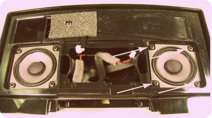
5. Amplifier PCB Assy Removal
5.1 Remove the four Phillips-head screws securing the Amplifier PCB Assy to the speaker housing as shown in figure
5.2 Using the heatsink fins and FF cable, carefully lift the Amplifier PCB Assy away from the speaker housing.
5.3 Disconnect the IR Receiver PCB FF cable and the Left & Right driver cables from the Amplifier PCB.
5.4 Amplifier PCB, see figure
5.5 Position the left and right driver harness as shown in figure. This will ensure that you don’t confuse the phasing of the drivers when reconnecting them to the PCB


6. Infrared Receiver PCB Removal
6.1 Peel back the foam tape concealing the IR Receiver PCB. See figure for details
6.2 Remove the Phillips-head screw securing the PCB in place
6.3 Disconnect the four conductor FF cable from the IR PCB.
Note: This cable provides signals to the
DSP IC via the Amplifier PCB.
6.2 Remove the Phillips-head screw securing the PCB in place
6.3 Disconnect the four conductor FF cable from the IR PCB.
Note: This cable provides signals to the
DSP IC via the Amplifier PCB.


7. Driver removal
7.1 Remove four phillips-head screws securing the driver to the speaker housing. See Figure
7.2 Note the routing of the driver harness before fully extracting the driver. See figure
7.3 Ensure acoustic foam is positioned behind the driver. See figure
7.2 Note the routing of the driver harness before fully extracting the driver. See figure
7.3 Ensure acoustic foam is positioned behind the driver. See figure

Subscribe to:
Post Comments (Atom)
Firmware : Bose Sounddock – Disassembling Procedure – Step By Step Disassembling Procedure – Audio System Repair And Service >>>>> Download Now
ReplyDelete>>>>> Download Full
Firmware : Bose Sounddock – Disassembling Procedure – Step By Step Disassembling Procedure – Audio System Repair And Service >>>>> Download LINK
>>>>> Download Now
Firmware : Bose Sounddock – Disassembling Procedure – Step By Step Disassembling Procedure – Audio System Repair And Service >>>>> Download Full
>>>>> Download LINK FI